TD-002
Reduction of Solder Crack/Low Elastic Modulus Material
Product form
| Prepreg | TD-002 |
Applications
- Electronic equipment for automobiles.
- Engine room set board.
- PCB on component packagings.
Features
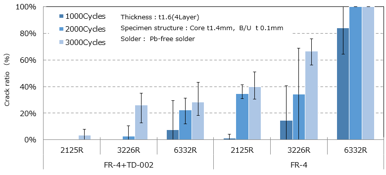
- Applied to PWB surface of standard material to absorb soldering stress and inhibit solder crack.
- Elastic modulus is 1/4 of that of standard FR-4.
- Enables to reduce solder crack without using high functional material by combining TD-002 with standard material.
Characteristics
Connection reliability of Pb-free solder [Thermal condition: -40℃ (30min.)⇔125℃ (30min.)]
Solder crack of TD-002+FR-4 (Cross section, after 3000cycles.)
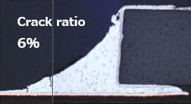
2125R
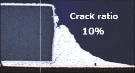
3226R
Elastic modulus
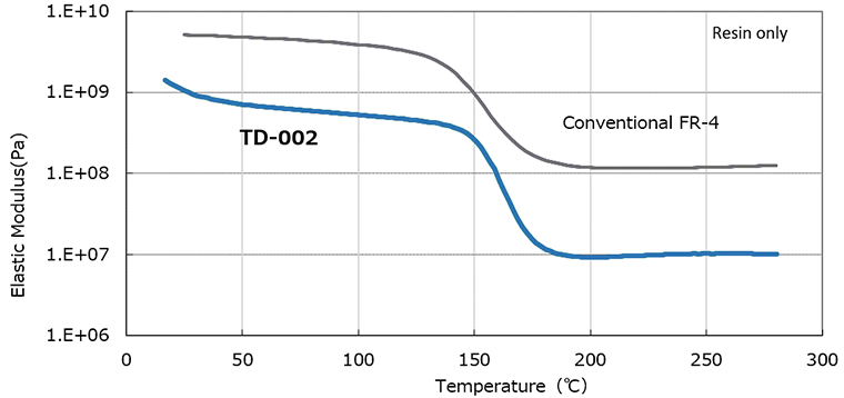
Elastic modulus
Mechanical drilling processing [After 3000 hits]
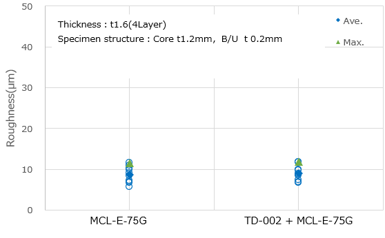
TD-002+MCL-E-75G
Appearance after drilling
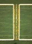
Conditions of mechanical drilling
- Stack-up: 3 panels
- Revolution: 120 krpm
- Drill bit: φ 0.3 mm
- E/B: Al t0.15mm
- Feeding speed: 2.4m/min.
Prepreg
(3313N58, t0.4mm, t0.1mm)
| Item | Condition ※3 | Unit | Actual Value | Reference (IPC-TM-650) |
||
|---|---|---|---|---|---|---|
| TD-002 | ||||||
| Tg | TMA method | A | ℃ | 155–170 | 2.4.24 | |
| CTE ※1 | X (30–120℃) | A | ppm/℃ | 6–9 | – | |
| Y (30–120℃) | 6–9 | |||||
| Z | <Tg | A | 80–130 | 2.4.24 | ||
| >Tg | A | 200–300 | ||||
| Solder Heat Resistance (260℃) | A | sec. | >300 | – | ||
| T-260 (Without Copper) | A | min. | >50 | 2.4.24.1 | ||
| T-288 (Without Copper) | A | >5 | ||||
| Decomposition Temperature (TGA method 5% Weight Loss) | A | ℃ | 345–360 | 2.3.40 | ||
| Copper Peel Strength | 18 µm | A | kN/m | 0.8–0.9 | 2.4.8 | |
| 35 µm | A | 0.9–1.1 | ||||
| Flexural Modulus (Lengthwise) | A | GPa | 5–8 | 2.4.4 | ||
| Elastic Modulus (Lengthwise) Tensile | A | GPa | 7–10 | – | ||
| Dielectric Constant | 1GHz ※2 | A | – | 3.6–3.8 | IEC-62810 | |
| Dissipation Factor | 1GHz ※2 | A | – | 0.011–0.013 | ||
| Volume Resistivity | C-96/40/90 | Ω・cm | 1×10¹⁴–1×10¹⁶ | 2.5.17 | ||
| Surface Resistance | C-96/40/90 | Ω | 1×10¹³–1×10¹⁵ | |||
| Insulation Resistance | A | Ω | 1×10¹⁴–1×10¹⁶ | – | ||
| D-2/100 | 1×10¹²–1×10¹⁴ | – | ||||
※1 Heating Rate: 10℃/min.
※2 Measured by cavity resonator.
※3 Refer to“Condition Note”
※ Above data are experimental results and not guaranteed.
Standard Specifications
Prepreg
| Part Number | Type | Glass Cloth | Properties | ||
|---|---|---|---|---|---|
| Style | Resin Content (%) |
Dielectric Thickness after Lamination ※1 (mm) |
|||
| TD-002 | 0.06 | (1037N77) | 1037 | 77±2 | 0.069 |
| 0.08 | (1078N66) | 1078 | 66±2 | 0.088 | |
| 0.10 | (3313N58) | 3313 | 58±2 | 0.115 | |
| 0.20 | (1501N54) | 1501 | 54±2 | 0.208 | |
| Reference (IPC-TM-650) | 2.3.16 | – | |||
※1 The dielectric thickness after lamination is defined as the thickness of one sheet of prepreg when the resin flow is 0%. This value changes depending on the press condition or inner layer pattern.
Inquirer about product
Please subscribe our technology eNewsletter!
Inquiry about product
Please inquire about product, technology or samples from here.